
| Back to home page |
|
|
IS-radarChirp-Ionosound |
 |
|
f = 154 + n*O.O15625 MHz (n = O,1,2,...,512)
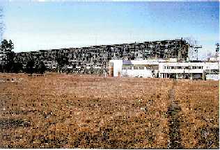
Two-positioned Chirp-Ionosound, constructed at ISTP.
Used for study of the ionospheric HF propagation and
diagnostics by oblique-incidence and backscatter techniques.
Regular observations are carried out in the north-east area of
Russia.
According to Pacific Region Equatorial Anomaly Studies in
Asia program (PREASA) Russian-Australian cooperative
experiments are carried out to study trans-equatorial HF
propagation.
A non-traditional approach, a mode theory is developed to
describe HF propagation. A simulation of oblique-incidence and
backscatter signals is fulfilled according to this theory.
Operative diagnostics prediction techniques of HF-circuits using
oblique-incidence and backscatter ionogramms are created.
| Win |